Carter Patent
Reprinted from "INSULATORS - Crown Jewels of the Wire", November 1972, page 5
To all whom it may concern:
Be it known that I, George Washington Carter, a citizen of the United States,
and resident of Canyonville, in the county of Douglas and State of Oregon, have
invented certain new and use improvements, of which the following is a
specification .
My invention is an improvement in insulators, and consists in certain novel
constructions and combinations of parts as will be hereinafter, described and
claimed.
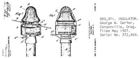
In the drawing Figure l is a perspective view of an insulator embodying my
improvements, and Fig. 2 illustrates a somewhat different construction within
the broad principles of the invention.
An important feature of my invention is what for convenience of reference I
term the two-color design. In practice I find it advisable to distinguish between the wire carrying a sufficient current of
electricity to make the same
dangerous to life and other wires carrying a current of lesser potentiality. In
carrying out this feature of my invention I make the body A of the insulator of
a light red or fire color and mark it with some distinguishing mark at A' which
in the construction shown consists of the words and figure "Oregon No. 1" and this with the color will indicate to any person that the wire
B on the insulator carries a current electricity of sufficient power to make
the same dangerous to life. The other insulator has its body C of any suitable
contrasting color such as the usual color of glass, and has the distinguishing mark C' consisting in to construction shown of the words and figure "Oregon
No. 2". These distinguishing marks A' and C' are placed on the outer side of
the insulator bodies near the lower end thereof and may preferably be molded
with raised characters, as will be understood from the drawing.
The insulator bodies are grooved at A2 and C2 for the reception of the line
wire B and the tie wire B' and the said bodies are provided at their upper ends
with means for securing a tie wire D or D' and the pegs E upon the upper ends
of which the insulator bodies fit are also provided with means for engagement to
the tie wires, the tie wires being utilized to hold the line wires to the
insulators and thus prevent crossing of the wire or sagging and thus protecting
the public and the workmen from contact with dangerous wires. As shown the pegs
E are provided with transverse openings E' below the insulator bodies and
through which the tie wire are passed.
In Fig. 1 the seat for the tie wire at the upper end of the insulator is a
transverse groove d formed in the upper end of the insulator body and receiving
the tie wire, the latter thus passing over the insulator body and through the
legs and being twisted at D2 to secure it so the line wire cannot become
displaced.
In Fig. 2, the seat for the tie wire at the upper end of the insulator body
is formed by a transverse opening d' formed through the insulator body and
through which the wire D' is passed and also passed through the openings E' in
the pegs E and twisted at D3 to secure it. By this construction I avoid any
displacement of the line wire holding the same permanently in connection with
the insulator body and also make the insulator bodies in contrasting colors so
they will indicate by the color as well as by distinguishing marks before
referred to the character of the current on the wire held to the insulator body.
I CLAIM:
1. The combination of an insulator body having between its ends a seat for a
line wire and provided at its upper end with a seat for a tie wire, a peg
fitting at its upper end in the insulator body and provided below the insulator
body with a seat for the tie wire, and a tie wire passing around the insulator
body and over the line wire and held above and below the line wire in the seats
of the insulator body and of the peg, substantially as set forth.
2. An insulator body having an annular groove for a line wire and its
fastening and provided above the said groove with a seat for a tie wire, and a
peg receiving the insulator body at its upper end and provided below said body
with a transverse opening, and a tie wire passed through said transverse opening
and around the insulator body and engaged with the upper seat thereof and having
its ends united whereby to retain the insulator body in connection with the peg
and the line wire in connection with the insulator body, substantially as set
forth.
3. An insulator body, a peg receiving the same, a line wire in connection
with the insulator body, and a tie wire passed around the insulator body and the
line wire and connected with the peg, substantially as set forth.
4. An insulator body grooved in its upper end to form a seat for a tie wire,
a peg receiving said body and having below the same a transverse opening for the
tie wire and a tie wire engaged with the groove in the upper end of the
insulator body and passed through the opening in the peg, substantially as set
forth.
GEORGE WASHINGTON CARTER
Witnesses:
Thos. Wilson
Henry Austen
| 
)